 Back to main page
Everyone teaching the subject of industrial instrumentation knows the value of realistic hands-on learning experiences for students, yet everyone teaching this subject knows how expensive the necessary equipment is and how daunting the task of setting up a lab environment to support these learning experiences. This page reveals some of the hard-won lessons I learned in doing this for the Instrumentation and Control Technology program I taught at Bellingham Technical College for 21 years.
When I first considered this problem, I immediately assumed the answer would take the form of hardware-based trainer modules which are a very popular solution for technical education programs. These consist of metal panels, usually on wheels, with piping, sensors, pumps, vessels, PLCs, and other equipment necessary to simulate the monitoring and control of some small-scale fluid process. They are also very expensive, typically tens of thousands of US dollars. Furthermore, they usually come with step-by-step ``lesson guides'' of limited academic value because they absolve students of the need to research information and to solve realistic problems.
So, why not just build my own trainers from industry-donated components? This would certainly save expenses, especially if students built them as part of their learning. However, this idea quickly soured as I realized just how many of these dedicated-process trainers I would need to have on hand in order to support a full Instrumentation program.
Then, the idea hit me: We don't have to buy or build dedicated trainer units at all. What we need is a system, or infrastructure if you will, allowing students to quickly and easily build, test, and disassemble miniature processes. All this system needs to have in place is the equipment that is universal to all processes: the controller (e.g. PLC, DCS, single-loop PID controller, etc.).
My solution to this problem was to build a loop system consisting of a control panel mounted in some central location in the lab room, with bundles of twisted-pair instrument cable running from this panel to various locations in the room, through field terminal panels with terminal blocks to marshall all the wiring connections. Students would set up field instruments (e.g. process transmitters, control valves, I/P transducers, etc.) at these remote locations in the room, commission them and draw up loop diagrams showing how they connect to the controller(s) in the main panel, and demonstrate their instruments' operation from that control panel.
My first year of trying this was the 2002-2003 instructional year. My budget was nearly zero. Our control panel consisted of a single NEMA-4X fiberglass enclosure that we happened to have on-hand from some past equipment donation, and a spool of cat-5 Ethernet cable rescued from the college's scrap metal bin. We mounted the panel to a hand railing on the mezzanine of our lab room where it overlooked the rest of the lab facility, and strung the cat-5 cable from this panel to multiple locations in the room, passing it through Euro-style terminal blocks every 20 feet or so. The cable was literally stapled to the walls, without conduit or cable tray of any kind. A single (donated) PID controller lived in the NEMA-4X panel, a Honeywell UDC 2000. A selector switch allowed this single controller to connect to multiple field cables, so that one student team (at a time) could energize their 4-20 mA loop to demonstrate its operation from the single controller.
As crude and as cheap as this system was, it functioned spectacularly. For the very first time my students had the experience of commissioning a real 4-20 mA instrument loop that was larger than a benchtop, and they could see for themselves how something they did here had an immediate effect on something else there. The system was spread out over a wide enough area that line-of-sight communication between the control room and the field location was often impossible, which led to another learning innovation: students had to use two-way radio units to talk with each other and coordinate efforts to commission and test their loops.
Field instruments (e.g. transmitters, I/P transducers, control valves) were already on-hand, most of these having been donated by local industries or purchased used. If you know what you're looking for and are willing to shop around at places like Omega.com, AutomationDirect.com, and Ebay, you may be surprised by how inexpensively you may outfit a functional lab with basic process sensors and controllers. Control valves are another matter, as these are large and considerably more expensive on the used market than transmitters, but if you have enough industry connections it is fairly easy to obtain donations of valves with known problems (e.g. leaking stem packings, plug/seat assemblies that cannot shut off tightly, etc.) that do not impede their use in a learning environment.
To this day I regret not keeping photographs of this crude ``loop system''. You can take my word for it that it was not pretty, but it still would be nice if I could show what we did with almost no capital investement.
My next opportunity to build a loop system came in the 2006-2007 academic year. I had been reassigned to teaching the first year (electronics) portion of the Instrumentation program after 2003, but in 2006 returned to teaching second-year courses where my students once again needed a robust lab facility. By this time the entire program had moved into a new building, but with that move my 2002-2003 prototype system got dismantled and never rebuilt.
Having learned the value of a ``loop system'' and knowing what a good investment it would be, I lobbied for some project funding and was able to obtain a few thousand dollars. My graphical pitch for the concept was this:
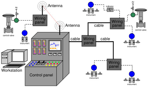
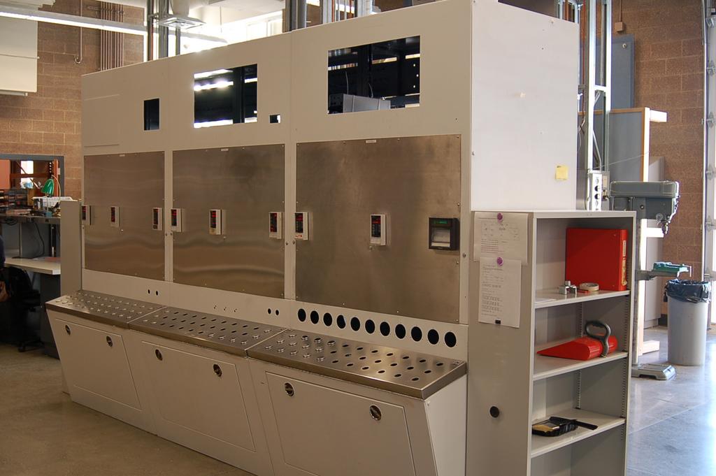
As before, all the field instruments would be temporary. Only the controller hardware, panels, and solid-line cables would be permanently-installed. I contacted local industry partners to see if they could donate a large control panel to be the centerpiece of this system, and we were able to get a large control panel from a pulp mill that was scrapping old equipment. We cleaned it up, gave it a nice paint job, and populated the panel with all the Siemens/Moore 352/353 single-loop controllers we had on hand:
Workbenches which used to fill this lab space gave way to racks made of ``unistrut'' metal framing, to which we bolted 2-inch vertical pipes for instrument mounting, and where we also bolted all of our donated control valves. A donated electrical enclosure comprised our main ``hub'' wiring panel, connected to the white control panel via a 2-inch PVC electrical conduit carrying several cat-5 cables:
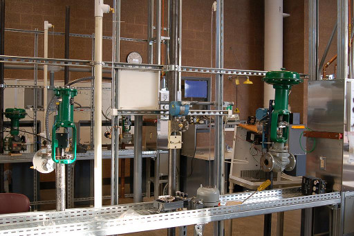
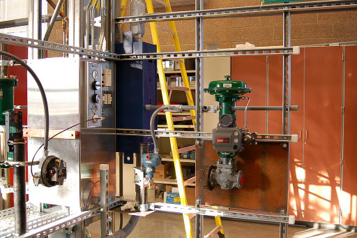
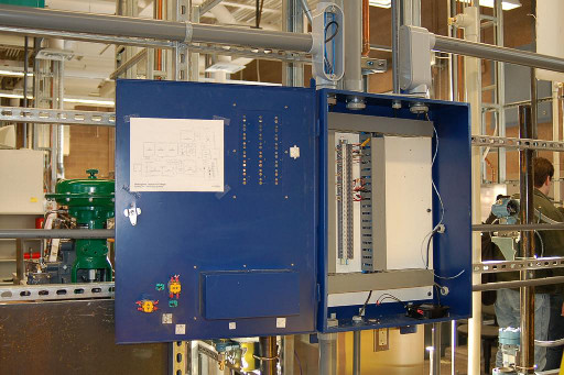
Smaller (1/2 inch) conduits branched out from this main junction box to locations along the metal-frame racks.
Many of our lab experiments consisted simply of connecting individual field instruments to the control panel through this cabling, without actually controlling any fluid processes. When a real process was necessary, we fabricated one at the field location from available hardware and controlled it using one of the panel-mount Siemens/Moore controllers, or using a PLC mounted in the same control panel.
One of the important lessons I learned from this experience is that the learning students obtained from using this ``loop system'' was far more practical than what they ever learned connecting instruments together on a workbench. The need to trace cables through panels, create loop diagrams to document their connections, commission loops while working between two or more locations in the room, etc. proved tremendously valuable when they graduated and gained employment as instrument technicians. The sense of realism also created excitement in their learning, as they perceived themselves doing ``real'' instrumentation work rather than bench-top exercises.
The Instrumentation program at BTC experienced significant growth since the first version of the ``loop system'' and at the end of the 2008-2009 academic year we realized we needed to expand the system to accommodate more students. One lesson learned from version 1.0 of the system is that ``unistrut'' metal framing is very expensive, and had burdened a disproportionate amount of our limited construction budget. This time around, we would need to find a cheaper alternative to unistrut.
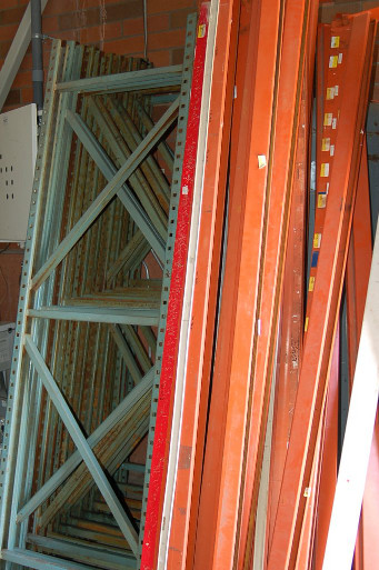
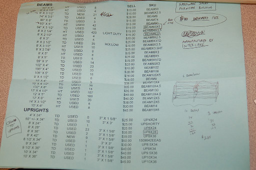
Such an alternative presented itself to me when I discovered I could purchase used pallet racks from a local hardware company. These are the metal racks used in hardware stores and other ``big-box'' retailers for shelving inventory. Robust and inexpensive, these racks proved much stronger than anything we built out of unistrut, and just a fraction of the cost. We dismantled most of our unistrut racks, then doubled the amount of rack space in our lab room using pallet racks, spending only $2000 on pallet racks and miscellaneous hardware. The old unistrut was re-used for other projects and also donated to an adjacent department for some of their lab projects.
These photos show the pallet rack components as we received them from the used-racking retailer (left) and the pricing sheet we received from them (right):
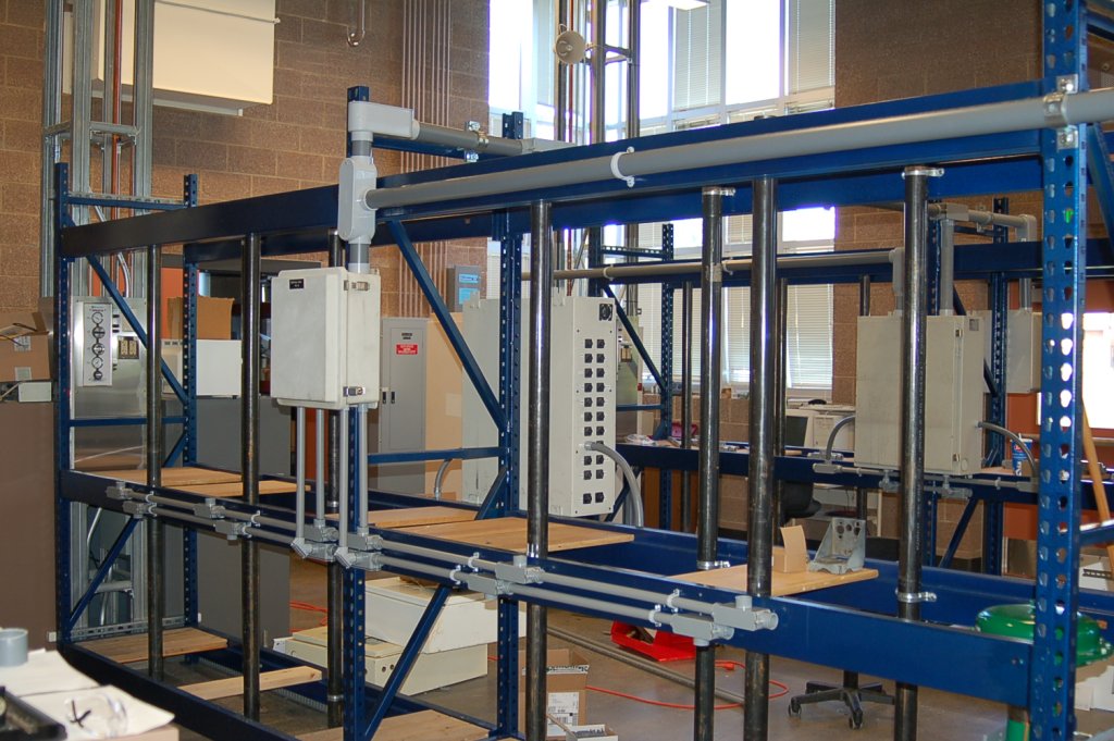
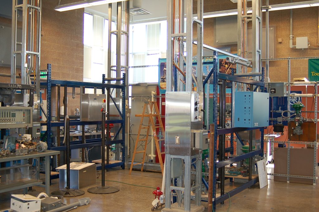
We sanded, re-painted, and assembled these racks in our lab room, complete with lengths of 2-inch vertical pipe to serve as mounting points for field instruments. I found multiple NEMA-1 electrical enclosures on Ebay to serve as field panels for the loop wiring, and we used 2-inch PVC electrical conduit to tie these field panels together. Instead of using cat-5 cable for our twisted-pair instrument signal wires, we instead used eight-conductor thermostat cable which was heavier-gauge and therefore less likely to break off with frequent student handling. views of the finished racks are shown below.
Permanently-installed cables connecting these field panels together did not directly connect to any field instruments, but merely landed on terminal blocks within those panels, awaiting connection to field wiring which the students would install with their temporary projects. Every field panel (junction box) was numbered, and each of these cables bore labels at each end consisting of the source and destination junction boxes. An illustration below shows how this worked:
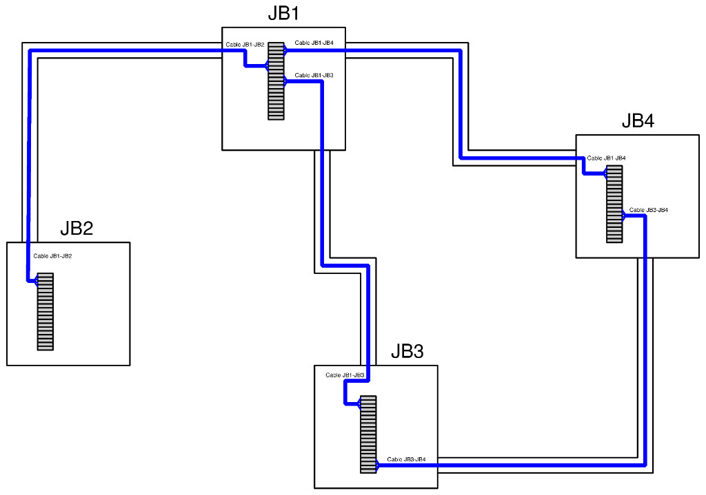
With this simple cabling in place, students could set up instrument loops spanning the entire lab room (e.g. transmitter near one junction box, controller at another, control valve at yet another) simply by connecting short twisted-pair cables to the field instruments and to the junction box terminals, as sometimes using ``patch cables'' as jumpers within a junction box to connect one trunk cable to another.
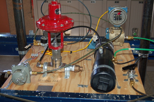
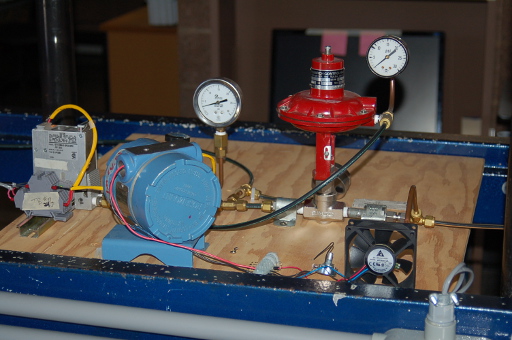
Our pallet racks proved useful in multiple ways. Not only were they cheap and strong support structures for heavy field instruments such as control valves (mounted low to keep the center of gravity as close to ground level as possible), but these same racks also served as shelving to hold small ``process boards'' made of plywood (2 feet square) upon which we bolted components to form miniature fluid processes. Photographs shown below highlight two of these process boards, the left photo being an air-pressure process and the right photo being a turbine speed-control process:
Air-based processes are far less troublesome than liquid-based processes, and so we tended to favor the former in our process board designs. We also discovered we could utilize the relatively large control valves we would receive from industry donations if we used air as the process fluid instead of water: a common vacuum-cleaner fan served well as an air pump, with pressure and flow characteristics well-suited to control valves with 2-inch or 4-inch flanged fittings, so we could perform air flow measurement and control rather easily.
Of course, there is nothing stopping an enterprising instructor (and students!) from constructing liquid-based process units for student projects, and that really is the point. Once you have a loop system in place, anything is possible. Process units may be added piece-meal as time and funding permits, while the infrastructure of panels, cables, racks, and controller equipment serves as the ``backbone'' for the construction of realistic systems ideally suited for the development of real-world instrument technician skills.