
GUN
SIGHT MARK 18
| The Gun Sight Mark 18 is an electrically operated, computing, reflector-type sight designed for use in power turrets. The gunner makes the proper settings on the control units, after which it is only necessary for him to "range and track" the enemy plane, for the sight automatically figures the proper point of aim. It makes no difference whether or not the enemy plane is in a pursuit curve, or whether the gunner is strafing a stationary target. This sight handles all situations equally well. It is not necessary for a gunner to be familiar with the internal construction of the Mark 18 |
Restricted
S-53
Gun Sight or the theory of how it computes deflections. Gunners should never dismantle or open up the sighting head or any of the other units. Only experienced maintenance men are allowed to replace units, alter adjustments or check for malfunctions, except as specified in "Boresighting" and "Gunner's Check." |
 |
GENERAL DESCRIPTION |
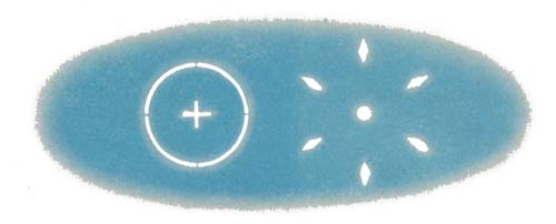
The Gun Sight Mark 18 is really two sights in one. It has two optical systems and two reticles. When you look at these reticles through the reflector plate they appear to be projected out into space. The reticle on the left which you view with your left eye resembles the inner ring of the Mk 9 reflector sight. This is the fixed reticle. The reticle on the right side of the reflector plate which you see with your right eye consists of a center "pipper" which is surrounded by six diamond-shaped pips arranged in the form of a circle. This is the gyro reticle or movable reticle. |
GYRO OR MOVABLE RETICLE |
The circle formed by the six diamond-shaped pips of the gyro or movable reticle can be made to spread out and close in. When you operate your turret the gyro reticle (the center pipper and six diamonds) moves around on the reflector plate. If you use the Mk 18 sight properly the gyro reticle automatically computes the correct deflection and gets hits for you. All you have to do is keep the enemy framed or "spanned" in an imaginary circle drawn so that it cuts the inside points of the six diamond pips of the gyro reticle. The center pipper of the gyro reticle, also forms the center of the imaginary circle. |
| THE FIXED RETICLE |
| The fixed reticle is essentially the same as the inner ring of the Mk 9 reflector sight. The only difference is that the center of the fixed reticle is a cross instead of a round pipper as in the Mk 9. The fixed cross indicates the direction that your guns are pointing. The fixed reticle is used for aligning the two reticle systems, for boresighting, for maintenance checks (also gunner's checks) and as a standby sight in case of malfunction or failure of the gyro reticle. Sighting with the fixed reticle is the same as with the Mk 9 sight, except it has only a one-rod ring whereas the Mk 9 has a one-rod and a two-rod ring. |
Restricted
S-54
| THE CONTROL UNITS |  |
| The complete Mk 18 sight installation consists of a number of units. Only those units that are of concern to you as a gunner are discussed. | |
| SIGHTING HEAD | |
| The sighting head is in reality the
sight. It contains the reflector plate through which you view the fixed
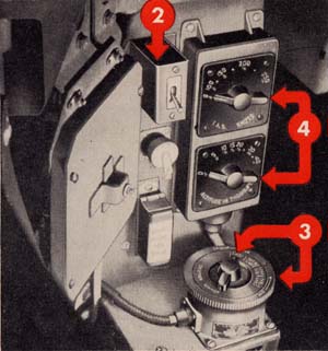
and gyro reticles. The lever on the right side of the sighting head is the sun filter control handle. Depressing this handle lowers the sun filter. On bright days the sun filter may be raised by lifting up the control handle. On the left side of the sighting head is the fixed reticle mask lever, which when depressed will blank out the ring of the fixed reticle and leave only the center cross showing. Below the fixed reticle mask lever is the range cable sheave, which is mechanically connected to the movable reticle and controls the movement of the six diamond-shaped pips. It is numbered in feet from 600 to 2400. Directly in front of you on the sighting head is the target span scale numbered from 30 to 120. These numbers represent the size of the target in feet. The target span lever can be moved from side to side to correspond with the known target dimension. Just under the target span scale and lever is a double-latched door which opens downward. Depress both latches to open the door, and mounted inside are two lamp bulbs which provide light for the two reticles. On the front of the sighting head (side farthest from you) is a small plastic container filled with blue material. This is the silica gel cell which |
Restricted
S-55
| dries out the air entering the sighting head and prevents the sight from
fogging up. The large cup or gyro pot to the side of the silica gel cell houses
the gyro and electromagnets of the computing mechanism. The small cup beneath the silica gel cell is the gyro motor housing. It houses the electric motor which turns the gyro. On the sighting head next to the gyro motor housing are two small screws. One screw cannot be turned unless the silica gel cell is removed. These two screws adjust the fixed mirror within the sighting head so that the fixed reticle can be aligned with the gyro reticle. The adjusting screw underneath the silica gel cell gives horizontal adjustment while the other gives vertical adjustment. An azimuth boresighting ring on the bottom of the sighting head is equipped with notches to permit movement of the sighting head. To move the sighting head right or left the number of notches necessary to harmonize the sight to the guns, loosen the mounting bracket bolt projecting from the bottom of the sighting head. To absorb shock, an "anti-vibration mount" is provided on the underside of the sighting head near the mounting bracket. |  |
| SELECTOR-DIMMER | |
| This
unit consists of a four-point switching device and a rheostat. It is usually mounted
near your left hand or on some other place you can reach easily. The "selector-dimmer
unit" enables you to turn on either the fixed reticle or the gyro reticle,
or both at the same time. On the face of the unit a pointer can be turned to any
one of the following four positions: FIXED—only fixed reticle visible in
reflector plate. This switch position is used for boresighting, maintenance checks,
gunner's checks and |
Restricted
S-56
| when the fixed reticle is used as a standby sight. FIXED & GYRO—fixed and gyro reticles visible in reflector plate. This switch position is used for day firing, for alignment of the two reticle systems and for gunner's checks. GYRO DAY—only gyro reticle visible. This switch position is optional for daytime firing. GYRO NIGHT—only gyro reticle visible. This switch position is used for night firing because the combat ranges are necessarily short. On the outer circumference of the selector-dimmer unit is a knurled ring (dimmer) which operates the rheostat controlling the brightness of the reticles. Turn the dimmer clockwise for greater brightness or counterclockwise for dimming the reticles. | |
| ALTITUDE AND AIRSPEED UNIT |  |
| This unit is mounted so that its numbers are visible and control
pointers easily reached. The upper half of this unit is the airspeed section and
is numbered in knots from 0 to 250. The indicated airspeed (IAS) of your plane is "set in" by moving the pointer to the correct figure. The lower half of the unit is the altitude section and is numbered in thousands of feet from 0 to 40. The altitude of your plane is "set in" by moving the pointer to the correct figure. | |
| OPERATING THE MARK 18 SIGHT | |
 | For Day Firing |
| BEFORE YOU SEE THE ENEMY | |
| 1
Turn on turret Main Power Switch (see Turret Section for location). 2 Turn on Sight Power Switch. 3 Turn Selector-Dimmer to "FIXED & GYRO" position; then turn knurled ring (dimmer) of this unit until the reticles have the desired amount of brightness. 4 Adjust the altitude and airspeed settings of your plane on Altitude and Airspeed Unit. During an attack, however, if your pilot is taking evasive action, do not use precious time resetting the altitude and airspeed. 5 Raise the sun filter if it is needed. | |
Restricted
S-57
| WHEN YOU SEE THE ENEMY |  |
1 Wingspan Setting As soon as you recognize the enemy plane, "set in" his wingspan on the target span scale. For example, if you recognize the enemy plane to be the Jap fighter "Hamp" you should know that his wingspan is 36 feet. Move the target span lever to the proper position on the target span scale. If you were attacking or being attacked by a Jap "Betty," set the target span scale at 70 feet. If you were being attacked by both, you must change the wingspan setting when you shift from one to the other. It is very important that you know enemy planes and their wingspans. Keep your knowledge of recognition up to date. |
 |  |
Restricted
S-58
 | 2 Ranging After you
have "set in" the correct wing-span of the enemy plane you must "range and track"
him properly if the sight is to compute the deflections. You "range" the enemy
by the use of the two foot pedals attached to cables in the turret. If you push
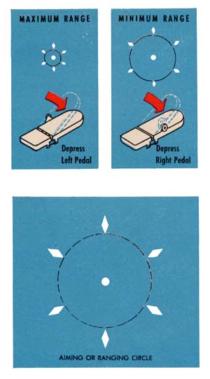
down on the right pedal the "aiming" or "ranging" circle (an imaginary circle
drawn through the inside points of the six diamond pips of the gyro reticle) gets
larger. In other words, the six diamonds move farther away from the center pipper,
thus making the aiming circle larger. This is minimum range. If you push all the
way down on the left pedal the diamonds move closer toward the center pipper and
the aiming circle is smaller. This is maximum range. It is very important that
you always keep the enemy "spanned" or framed within the aiming circle if you
want to get hits. |
Restricted
S-59
| will touch each side of the ranging circle. He is now "spanned" and in range. Open fire. He appears to get larger as he gets closer. It will be necessary for you to make the aiming circle get larger and larger in order to keep it just touching his wingtips. You do this by pressing down on the right pedal gradually and smoothly. You must track him carefully and keep him accurately spanned or you will not get hits. Then just keep the center pipper right on the spot you want to hit and watch Hamp fall to pieces. If an enemy gets within 600 feet of you the ranging circle will not get any larger. This does not mean that the sight is not accurate within 600 feet. It is very accurate. All you have to do now is hold the right pedal all the way down and keep the pipper where you want to hit. |  |
Sometimes it may not be possible for you to span on a full-square
view of the enemy's wingspan. If you have a full-square view of the enemy plane's
fuselage instead of the wings, you still set the wingspan of the enemy on the
target span scale. However, keep the pipper on the cockpit and one edge of the
aiming circle on his tail and you will have him "spanned" properly. This is because
enemy fighters are approximately one-half as long from cockpit to tail as from
wingtip to wingtip. 3 Tracking As the attacking enemy moves in, you must operate your turret to keep him framed within the ranging circle. This is referred to as "tracking." Frequently it will be necessary for you to move your turret rapidly at first to pick up your target. This is called | |
Restricted
S-60
"slewing." Always keep the right pedal fully depressed while slewing the turret, regardless of the range of the enemy. Otherwise the gyro reticle will "tumble" (drift entirely off the reflector plate) and the sight will be out of commission momentarily. Therefore, when slewing pick up the target with the fixed reticle and swing ahead of it along its line of apparent motion. The fixed reticle shows where your guns are pointing. To help the gyro reticle to "catch up," reverse the direction of slewing along the target path; then depress the left pedal to frame the target with the gyro reticle. Track smoothly for a moment and then open fire. When you are on the target your tracking must be smooth and deliberate. The sight will not compute properly if your tracking is jerky. After you have spanned the target always track a short distance before opening fire to enable the sight computing mechanism to figure deflection. For Night Firing 1
Turn on turret Main Power Switch. Firing with Fixed Reticle If for any reason the gyro reticle system does not function properly or fails to function, use the "fixed reticle" as a standby sight. To use the fixed reticle turn selector-dimmer to the "Fixed" position; turn the dimmer to adjust the brightness of the reticle; and then use the fixed reticle the same way you would a Mk 9 sight. The fixed reticle has a 35 mil radius—one rod. |
| BORESIGHTING |
Boresighting the Gun Sight Mark 18 establishes a parallel relationship between the center of the fixed cross of the fixed reticle and the bore axes of the guns. Before boresighting this sight, the fixed and gyro reticles must be aligned. They are aligned when the center pipper of the gyro reticle and the center of the fixed cross of the fixed reticle are super- imposed at an infinite distance with no windage, gravity or relative speed allowances in the system. ALIGNMENT CHECK 1
Turn the selector-dimmer unit to the "FIXED" position. |
Restricted
S-61
3
Turn the selector-dimmer to "GYRO NIGHT." The center pipper of the gyro
reticle should bear within one mil upon the object on which the fixed cross was
sighted. (The diameter of the pipper is approximately two mils.) If the sight
fails the above test, the fixed mirror is out of adjustment. ALIGNMENT ADJUSTMENT 1
Secure the optical gage in position on the sighting head. The gage brings the
patterns of both reticles into one line of vision when, without the aid of a distant
reference point, both reticle patterns are observed at the same time. BORESIGHTING PROCEDURE 1
Level the airplane athwartships and longitudinally. |
Restricted
S-62
5 Adjust the sighting head so that the center of the fixed cross bears upon the same distant object. NOTE: It is not necessary to allow for gravity drop
of the projectile. The sight automatically compensates for this. |
| GUNNER'S CHECK |
The most expert and painstaking maintenance of this gun sight, as of any gun sight, will not insure accurate results if the turret is operating badly. Make sure your turret is checked and serviced frequently. PRE-FLIGHT INSPECTION 1
Test the sun filter's operation and the fixed reticle mask lever. Check that all
glass surfaces are clean; use lens paper for cleaning. Make sure the range cable
sheave does not rotate when the sighting head is moved back and forth on its sliders
or when the guns are elevated or depressed. |
Restricted
S-63
smooth operation. Check that the fully depressed position
of the left and right pedals against the stops corresponds to 2400 and 600 feet
respectively on the range unit sheave. Check that the override springs do not
"give" before the pedals reach the stops. Check that 1250 feet on the
range unit sheave corresponds to 1250 feet on the range cable sheave on the sighting
head. PIPPER CHECK Use the optical gage if there is no distant object to employ as a target. The figures that follow are not to exact scale, so the positions are relative. For clarity, the six diamond-shaped pips are not shown. The check will be easier to understand if you remember that the fixed cross is boresighted to the guns; therefore, the allowance between the fixed cross and gyro pipper illustrates the angle between the sight axis and the gun bore. Unless your plane is connected to an external power supply, operate the turret manually—do not use plane batteries. ALIGNMENT If the cross and pipper are not aligned, make the necessary adjustments. (See Boresighting Instructions.) | |
MAKE PIPPER CHECK AS FOLLOWS | |
SELECTOR-DIMMER UNIT | |
FIXED 1 Turn the selector to "FIXED." 2 Note the fixed reticle pattern. The ring may be blacked out by action of the mask lever. The gyro motor should not run. See Figure 2. 3
Run the dimmer ring from dim to bright and note the increase in reticle brilliance. |  |
Restricted
S-64
FIXED & GYRO 1 Turn the selector to "FIXED & GYRO." 2 Both fixed and gyro reticles should be visible and the gyro motor should run. The gyro reticle pipper should be directly below the fixed cross; this is the gravity allowance. See Figure 3. |  |
3
Turn the turret slowly in azimuth to the right and note that the gyro reticle
pipper lags the fixed cross. See Figure 4. Continue to turn the turret at the
same speed and shift rapidly to short range. Note that the lag effect is less
at short range. See Figure 5. Repeat the above while rotating the turret in the
opposite direction and at the same speed. The deflections should be the same as
the above, but in the opposite direction. |  |
GYRO DAY 1 Note the azimuth deflection, which indicates that the guns are pointing ahead of the sight axis. The fixed reticle disappears and the gyro reticle remains stationary when the selector is turned to "GYRO DAY." The faded reticle in Figure 7 is for reference only. 2
Note the difference between Figure 3 and Figure 6. Windage deflections are not
generated when the airspeed is zero. | 
|
Restricted
S-65
FIXED NIGHT 1
When the selector is turned from "GYRO DAY" to "GYRO NIGHT"
the gyro reticle pattern should shift to the left as in Figure 9. Faded reticle
is for reference only. Movement can be observed by selecting a distant reference
point in the field of view corresponding to the position of the fixed cross. No
windage or gravity deflections are generated. |  |
| RANGE UNIT | |
FIXED NIGHT 1 Note that as the range is changed from maximum to minimum, the gyro pipper shifts to the left and almost touches the fixed cross. This illustrates the smaller allowance needed between the sight axis and gun bore at short ranges. Also note that at short range the allowance for gravity drop is less. | 
|
| ALTITUDE AND AIRSPEED UNIT | |
ALTITUDE CHECK 1
Note that as the altitude control pointer is turned from zero to maximum altitude
the gyro reticle pipper moves to the left toward the fixed cross. Its position
is halfway between the fixed cross and the zero altitude position. This illustrates
that at high altitudes, the air being less dense, the bullet travels faster, so
a smaller allowance is needed. See Figure 11. | 
|
Restricted
S-66
AIRSPEED CHECK 1
As the airspeed control pointer is turned from maximum to minimum, the gyro reticle
pipper moves to the left, and at zero airspeed it lies directly below the fixed
reticle cross. This illustrates the fact that at zero airspeed no windage allowances
are needed. |  |
| |
| AZIMUTH UNIT | |
1 With turret at 0° or 180° the gyro reticle pipper should be directly under the fixed cross as in Figure 13. When firing directly fore or aft, no azimuth windage allowances are needed. | 
|
2 With the turret at 90° azimuth, the gyro reticle pipper moves to the right of the fixed cross as shown in Figure 14. With the turret at 270° azimuth, the gyro reticle pipper moves to the left of the cross as shown in Figure 14. Both positions illustrate the guns pointing ahead of the sight axis. | 
|
| ELEVATION UNIT | |
In
the early production units, there is a dead zone beyond 82V2° elevation and
depression; so, the pipper deflection will drop to zero. If this condition exists,
only elevate or depress 82V2° when making the test. In later units there is
no dead zone. | 
|
Restricted
S-67
2
With the turret at zero azimuth, 90° elevation, the pipper shifts to a point
directly above the cross. If the guns are swung to maximum depression (90°),
the gyro pipper will shift to a point considerably below the cross. The positions
are illustrated in Figure 16. Note that in both positions the guns point ahead
of the sight axis. |  |
3
With the turret at 180° azimuth and the guns at 0° elevation the pipper
shifts to a point directly below the fixed cross. | 
|
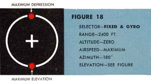
4 With the turret at 180° azimuth and the guns at maximum elevation (90°), the pipper shifts to a point directly below the fixed cross. If the guns are swung to maximum depression (90°), the gyro pipper shifts to a point directly above the fixed cross. Positions are illustrated in Figure 18. Note that in both positions the guns are pointed ahead of the sight axis. | 
|
5 With the control positions as indicated under Figure 19, there is the allowable gravity deflection but no azimuth windage allowance. | 
|
6
As the guns are elevated or depressed, the gyro pipper moves toward the center
of the fixed cross. At 90° elevation or depression, the pipper should be at
the center of the cross. This action indicates that the gravity shunt is working
properly. | 
|
Restricted
S-68